

Search
T-molding appears simple, but reliable retention depends on the relationship between the face, stem, barbs, routed groove, and substrate. Ordering by face width alone can produce a profile that looks correct yet pulls out, buckles around a curve, or leaves the panel edge exposed.
A production drawing should define the mating groove and the molding together. Both parts have tolerances, and the allowed stack-up must hold across tool wear, material lots, and climate.
Visible face width and crown shape
Stem thickness, stem depth, and centerline position
Barb width, barb angle, pitch, and number of engagement points
Nominal groove width, depth, and corner radius
Finished panel thickness and permitted face overhang
Minimum inside and outside bend radius
Cut-length, coil, or roll packaging requirement
When selecting t molding edge banding, ask for a cross-sectional drawing of the proposed profile. A physical sample remains important because barb recovery, surface finish, and flexibility cannot be judged from nominal dimensions alone.
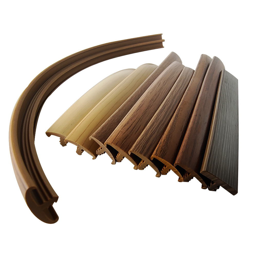
Retention comes from elastic deformation and barb engagement. If the groove is too narrow, installation force rises and the substrate may split or the stem may stretch. If it is too wide, the molding can lift during handling or thermal cycling.
Route test grooves at the low, nominal, and high limits. Measure actual cutter runout and groove width rather than relying only on the cutter label. Porous MDF, plywood, and solid wood can require different interference because their edge strength and spring-back differ.
| Condition | Common risk | Design response |
|---|---|---|
| Tight inside radius | Face wrinkles or stem compression | Increase radius or use a more flexible construction |
| Tight outside radius | Face whitening or pull-out | Increase radius and control installation tension |
| Compound contour | Face twist | Prototype on the real routed path |
| Cold installation | Higher stiffness and cracking risk | Define conditioning and line temperature |
Do not stretch the molding to make it follow a curve. The stored tension can pull the ends back after cutting. Allow the profile to relax, control feed tension, and define end treatment in the assembly instruction.
PVC, ABS, and other thermoplastic constructions differ in stiffness, recovery, impact behavior, and temperature response. Metallic, printed, or high-gloss surfaces may also show stress marks more readily. Specify color, gloss, texture, and acceptable visual limits with the mechanical dimensions.
For color matching, approve samples under agreed light sources and viewing geometry. Maintain a master standard and record the profile lot; a digital color value alone may not capture texture and gloss effects.
Approve the profile drawing and mating groove limits.
Trial low/nominal/high groove sizes on production substrate.
Measure insertion force and pull-out resistance at several positions.
Build the tightest real corner and condition it hot/cold.
Inspect face coverage, joint appearance, and end relaxation.
Freeze the cutter, line settings, and golden sample.
It depends on the stem and barb geometry, material, and substrate. Use the supplier drawing and validate a tolerance range on production panels.
Possibly, but retention and splitting risk can differ. Test the exact groove in each substrate.
The radius may be too tight, the groove may be oversized, or installation tension may be pulling the profile back.
Some designs are mechanical-fit only; others use adhesive for severe service. Confirm compatibility and rework requirements before adding glue.
For a custom or standard RUIZHAN profile, provide the panel material, thickness, groove limits, minimum radius, service temperature, finish, quantity, and drawing format. A matched sample-and-groove trial gives a more reliable approval than face-width selection alone.